By Lukas Lechthaler, Thomas Gries, Richard Kupke, Dirk Feltin, Peter Vojcena, Christine Stamm
The aim of the research project “ZIM EddySCARF” is the development of an eddy current sensor, which allows inline, non-contact 100-percent inspection of carbon fiber rovings for quality assurance. The sensor is useful to both carbon fiber manufacturers for outgoing goods inspection and yarn-processors as means of incoming goods inspection and production process monitoring. The eddy current sensor is intended to detect, classify and quantify various defects in carbon fiber processing — gaps, fuzz, undulations, false twists, accumulated or significant filament breaks, for example. The evaluation of the measurement signal is carried out both by classical measurement value analysis and by machine learning algorithms using neural networks. The focus of the development is on the detection of optically invisible defects and their influence on mechanical performance. The economic use of the sensor by scaling is of secondary interest.
Challenges
Carbon fiber reinforced plastics (CFRP) are becoming increasingly important in various fields of application. The largest areas of application are in the aerospace and automotive industries, with the wind energy and sports and leisure sectors also recording growth [CC18]. Quality assurance has already been certified for metallic materials and corresponding test procedures exist. In contrast, both testing and quality assurance of the CFRP process chain are still under development. The quality assurance of carbon fiber (CF) rovings is the sole focus of this project. When a damaged roving is removed early from the CFRP process, no added value is wasted as is not processed into a component. In this way, a suitable test procedure can contribute to increased economic efficiency and resource conservation of the energy- and cost-intensive material carbon.
So far, the quality assurance of carbon fiber rovings has been carried out offline by means of outgoing and incoming goods inspections using destructive testing. These tests are time-consuming and can only be carried out in the form of sampling. Therefore, a carbon fiber bobbin cannot be tested 100 percent, which results in an uncertainty regarding the quality of the goods. In order to realize a 100 percent inspection, non-destructive testing methods can be used, whereby at this time mostly optical sensors are used. A disadvantage of optical sensor systems is that quality assurance can only be performed on the surface of the roving. However, in a 12k roving (see Figure 1) only about 1,900 filaments are on the surface, while the roving consists of a total of 12,000 filaments [Mor05; Sch07].

Figure 1 shows that optical sensors can only detect around 16 percent of the roving. Defects inside the roving are therefore not detected and remain in the process chain, where they can ultimately lead to waste. Furthermore, CFRP components are heavily oversized due to defects that cannot be detected and for safety reasons. The safety factors for standard components range from j = 1.5 [Sch07] to j = 3 for safety-critical components. These are the direct consequences of defects in the carbon fibre roving caused during processing which cannot be detected with the current state of the art. This thus contributes to the relatively high production costs of CFRP components. One approach to detect hidden filament breaks by optical sensor technology is the use of destructive testing methods. This also allows the inside of the CF roving to be made optically accessible. However, the disadvantages of destructive testing methods, such as test waste of the cost-intensive material carbon and the lack of the possibility for use in inline process monitoring, oppose this approach.
Aim and Approach
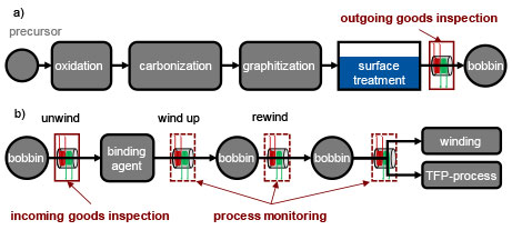
Therefore, the aim of the research project EddySCARF is the development and application of a stand-alone, inline filament breakage sensor based on the physical functional principle “eddy current” (EC) (SURAGUS GmbH). The EC sensor is intended to achieve 100 percent inline process monitoring of carbon fiber-based manufacturing processes. This will be carried out using the example of structural components in the aerospace industry for quality-controlled process monitoring and control. The sensor system can be used both by carbon fiber manufacturers such as Teijin Europe GmbH, and processors including Hightex Verstärkungsstrukturen GmbH or SAERTEX GmbH & Co. KG, all based in Germany. For carbon fiber manufacturers, quality monitoring by means of eddy current is intended to enable a 100-percent outgoing goods inspection. For carbon fiber processors, the aim is to quantify fiber damage along their process chain by using eddy current so that the various sub-processes can be optimized and a 100 percent incoming goods inspection made possible. Figure 2 shows potential applications of the eddy current sensor system at carbon fiber manufacturers and processors.
The measuring system can reduce production waste and improve material usage. As a result, the lightweight construction factor of the material carbon is exploited to a greater extent. The sensor’s application possibilities are broadly diversified due to its flexible use along the CFRP process chain by both manufacturers and processors.
Solution
First, the requirements of all project partners for the eddy current sensor system are defined. For this purpose, the requirements of carbon fiber manufacturers, represented in the research project by the Teijin company, as well as those of carbon fibre processors, represented in the project by the companies Hightex and SAERTEX, are taken into account. At the same time, a test bench for validating the eddy current sensor will be developed, manufactured and commissioned at the Institute of Textile Technology. On the test bench, artificial defects similar to those during production and processing can be inserted into a carbon fiber and measured. A so called damaging module will be developed and implemented in the test bench, which allows a reproducible application of the defects, so that the eddy current sensor can be tested here on a laboratory scale. Figure 3 shows a schematic representation of the tribological test bench on which the eddy current sensor is tested.
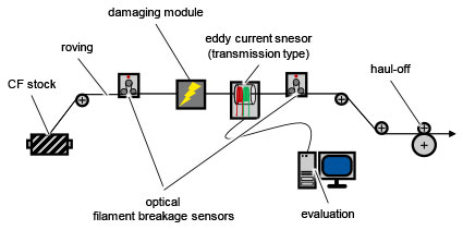
On the test bench shown in Figure 3, a carbon fiber roving is measured via optical filament breakage sensors to quantify the superficial degree of damage before and after contact with the damaging module. Via the damaging module, defects are automatically and reproducibly inserted to the roving and subsequently detected with the eddy current sensor. By automating the damaging module, both the location and type of the defect are known, so that it can be correlated with the measurement signal of the eddy current signal and compared with the data of the optical filament breakage sensors. The approaches pursued in the project to evaluate the eddy current signal are both in the classical measurement value analysis and in the use of machine learning algorithms using neural networks.
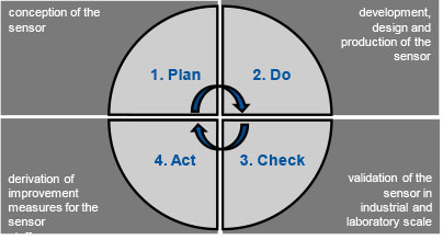
The eddy current sensor itself is developed in an agile and iterative way and follows the four stages of a Deming cycle (See Figure 4). First, the sensor prototype is designed and manufactured by SURAGUS. Afterwards the sensor is validated in laboratory scale at the Institute of Textile Technology as well as with the research partners under real production conditions in an industrial environment. The sensor will be used by the different project partners in different processes. Hightex implements the sensor system in the Tailored Fibre Placement, SAERTEX in the scrim production for the qualitative control of the carbon fiber bobbins and Teijin in the carbon fiber production process and compares the measurement signal with real production data. Finally, improvement measures for the measuring system are derived from the use on a laboratory and industrial scale (4th Act) in order to be able to counter the problems identified in the process. Subsequently, the cycle is run through again in order to realize a progressive improvement of the sensor over the project duration, starting with a first prototype up to an industrially usable sensor system.
Initial tests have already shown that filament breaks introduced specifically into carbon fiber rovings lead to a significant deflection in the measurement signal. For this purpose, a roving was damaged on the test bench shown in Figure 3 and the damage applied was measured using a first prototype of the eddy current sensor. The roving was tested at a haul-off speed of 2 meters per minute for 5 minutes per test point and without additional yarn tension. Each test point (a-g) of the preliminary tests in Figure 5 thus corresponds to a tested run length of 10 m carbon fiber and represents approximately 7,000 measuring points.
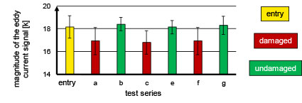
The results of the preliminary tests show a difference between the measured values of the damaged areas (a, c, f) and the undamaged areas (b, e, g). The magnitude of the eddy current signal was recorded as the measured value. The available results of the preliminary tests show that the measuring principle eddy current is suitable for the detection of filament breaks. A challenge, however, is the high standard deviation of the damaged carbon fiber, which still allows a statistically secured differentiation between damaged and undamaged areas of the carbon fiber. However, the sensor used is the first prototype, which does not yet incorporate the findings and improvements from validation on a laboratory scale and in an industrial environment. Therefore, a significant improvement is expected with each run of the Deming development cycle, so that after proof of a statistically secured detection of filament damage, the resolution and measurement sensitivity of the sensor can be addressed.
Acknowledgement: The research project ZF4558940WM9 of AiF Projekt GmbH, Berlin is funded by the Federal Ministry of Economics and Energy (BMWi) within the framework of the Central Innovation Programme for SMEs (ZIM) based on a resolution of the German Bundestag
References:
[CC18] Carbon Composites
Composites-Marktbericht 2018 – Marktentwicklungen, Trends, Ausblicke und Herausforderungen, 2018
[Ehr06]
Ehrenstein, Gottfried Wilhelm
Faserverbund-Kunststoffe. – München: Carl Hanser Verlag GmbH & Co. KG, 2006
[Mor05]
Morgan, Peter
Carbon fibers and their composites. – Boca Raton: Taylor & Francis, 2005
[Sch07]
Schürmann, Helmut
Konstruieren mit Faser-Kunststoff-Verbunden. – Berlin, Heidelberg: Springer-Verlag Berlin Heidelberg, 2007
Editor’s Note: Lukas Lechthaler is a researcher and Thomas Gries is director of the Institut für Textiltechnik of RWTH Aachen University; Richard Kupke is director of product management at SURAGUS GmbH; Dirk Feltin is CEO of Hightex Verstärkungsstrukturen GmbH; Peter Vojcena works in system development NCF Inspection at SAERTEX GmbH & Co. KG; and Christine Stamm is manager, technical service at Teijin Carbon Europe GmbH.
August 13, 2020