 Printed electronics enable e-textiles and wearables powered by radio frequency wireless power.
By Charles Goetz
A runner returns home after putting in a solid 5K run. They check their heart rate maximum and peak breathing rate using a smart phone, then remove their fitness tracking shirt before showering. Instead of removing an electronics package from the garment, they can toss it directly into the laundry because those electronics are embedded directly into the e-textile, making the garment machine washable. At the end of the wash cycle, the shirt hangs to dry in the closet where it also wirelessly recharges to be ready for the next run.
This may sound like an advertisement from the future, but implementing a wireless charging system into e-textiles and other wearables is possible today.
Wireless Charging At A Glance
A variety of wireless charging technologies are available, including magnetic resonance, ultrasound, radio frequency (RF) and Qi — inductive coupling. The longest-range option, and also the topic of this article, is RF. This technology sends a trickle charge over the air and allows a “set it and forget it” convenience where users can simply place or hang an e-textile near the transmitter without having to worry about exact alignment for charging.
An RF wireless power system consists of two sides:
- A transmitter, Tx, placed near the e-textile such as in a closet or drawer; and
- A receiver, Rx, embedded into the e-textile.
The RF transmitter, Tx, in the charging system emits radio waves at a specific frequency. The receiving antenna, Rx, and matching network then harvest that RF from the air, while a converter chip converts the RF into usable DC power (see Figure 1).
Elements To Consider When Designing An RF Wireless Power System
Transmit—Tx: Frequency, power level, and antenna gain are the three key elements for an RF power transmitter. First, the country where the transmitter will operate shapes its design — local frequency band allocations and power output limits dictate how much power the device can transmit and at what frequencies. For example, in the United States, the Federal Communications Commission (FCC) governs all radio equipment. Part 15 of the FCC’s rules limits power fed to the Tx antenna to a total of 30 decibel-milliwatts (dBm), or 1 Watt, and limits antenna gain to 6 decibels relative to isotropic (dBi), for a maximum of 36 dBm, or 4 Watts, of effective isotropic radiated power (EIRP). Different combinations of output power and antenna gain are allowed, but the limit of 4W EIRP remains.
This FCC rule applies to all unlicensed communication devices operating across three frequency bands — 902-928 megahertz (MHz), 2.40-2.483 gigahertz (GHz), and 5.725-5.875 GHz. Transmitters used in the United States must comply with these limits.
Each country has its own rules and restrictions for frequency allocations, power output limits, and emission requirements for radio transmitting devices.
Receive—Rx: Luckily, the receiver side of the wireless power network is simpler to design because wireless power receivers generally require no local communications certifications. There are three main variables to consider — frequency, antenna gain, and expected received input power range related to the distance from the transmitter.
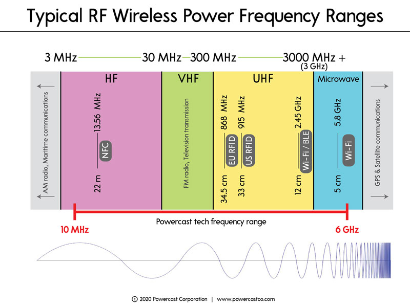
Let’s start with frequency. Designers can calculate the level of received RF power over a given distance in the far field using Friis equation. This equation shows that lower radio frequencies tend to deliver power more efficiently than higher frequencies under the same circumstances, for example, the same Tx power, Tx antenna gain and Rx antenna gain (see Figure 2).
The chosen frequency impacts the charging distance in an RF wireless power network (WPN). At lower frequencies, like those in common RFID industrial, scientific and medical (ISM) bands, receivers can generally operate further away from the transmitter and tend to offer superior charging time. On the other hand, WPNs operating at higher frequencies, such as 2.45 GHz, can accommodate smaller antennas on both the Tx and Rx ends, appealing to both engineers and chief technology officers in today’s quest to achieve increasingly-smaller devices.
Next, how much power does the receiver need? The Friis equation demonstrates that the received power drops off as one over distance squared. This means that power-hungry wearables will need to charge close to a Tx source, while lower power devices such as sensors can charge at much greater distances.
Lastly, let’s discuss antenna gain. Higher gain antennas capture more RF power but inherently become more directional. Lower gain antennas are omni-directional, meaning they can receive RF power from almost all directions.
In e-textiles like a fitness shirt, it is possible to implement multiple receiving antennas and get the best of both worlds — multiple antennas capture more RF power like high-gain antennas, but also can have omni-directional patterns like low-gain antennas.
A WPN, frequency, antenna gain, and input power are all intertwined. Designers cannot adjust one without affecting another, so should consider all equally when designing both the wireless power delivery network and one or more receive devices.
Game-Changing Printed Electronics
Luckily, a shirt or pair of shorts provides a large footprint for printing electronics, unlike small earbuds, fitness trackers, or hearing aids that take up less physical space. The entire garment can serve as an electronic canvas for implementing circuitry, screens, buttons, and antenna(s) (See Figure 3).
For recharging, consumers will simply place a wireless power transmitter in the closet or drawer near where they store or hang their smart wearables. Close-range charging and a large physical footprint make wireless charging a natural solution for smart garments.
Fast Charging, Large Footprint
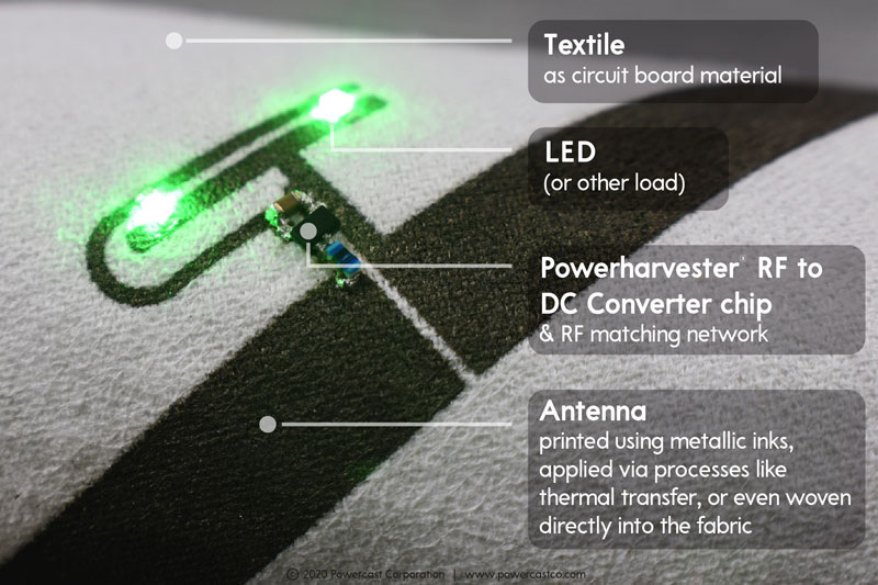
Rigid or rigid-flex electronic circuit boards are obviously a hindrance in smart garments. Luckily, when printing electronics onto e-textiles, the garment itself becomes the circuit board and it can still bend and flex. Circuitry can be directly printed onto garments using conductive materials like Pittsburgh-based Liquid X®’s particle-free metallic inks, or applied via thermal transfer using technology from companies such as England-based Conductive Transfers Ltd. These printed electronics breakthroughs — conventionally printable conductive inks and thermal trace transfer — have opened the gates for consumer smart garments.
When creating a wirelessly rechargeable smart garment using RF wireless power, the entire garment may be used as a canvas. Multiple power-receiving antennas may be printed on the garment, which creates a large area to capture the RF energy sent over the air from the transmitter and will increase the garment’s overall charging speed. Then, other small electronic components can be mounted onto the printed traces, including the tiny wireless power chip that converts the RF energy into usable DC power; a battery; and any other components that add desired functionality such as sensors, LEDs, alarms, GPS tracking, or even bistable displays. Finally, to make the garment washable, an encapsulant can provide a high-strength waterproof bond to seal in all of the electronic components.
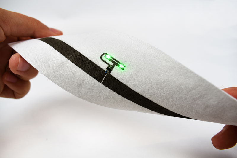
bend without harming the embedded electronics.
The ability to embed electronics into smart garments that are flexible, durable and washable, and eliminate traditional rigid and fragile electronics packages, is a game changer (see Figure 4).
Battery Considerations
With the functionality of today’s smart garments sometimes stifled by battery size and also the need to detach the battery for recharging and washing, a low-effort wireless recharging system could instead deliver advanced e-textiles to the everyday user.
Today’s smart garment manufacturers often use large batteries that can last multiple sessions without recharging, because disconnecting a battery pack before washing the garment and plugging it in to recharge, can feel cumbersome to an ordinary user.
If a user no longer has to think about the recharging process and can instead follow a typical routine of washing and hanging the garment, then smaller, single-wear batteries become viable. Implementing a low-effort wireless charging system can enable designers to deploy single-wear batteries. The entire capacity of the maximum tolerable battery size could then be used for the duration of a single session, so manufacturers can either enhance the garment to perform additional functions; or, physically shrink battery size to create a more lightweight, less bulky end product.
The Future Of The Wireless Charging Closet
Advanced e-textiles have been deployed in military and industrial settings, and are expanding into the consumer market as well. But a dead battery pack renders e-textiles useless. Integrating RF wireless power networks to replace battery packs and ensure frictionless, easy-to-use recharging is one path to avoid such failures. Wired charging will only last as far as the cord can reach, and the tech community is quickly approaching that juncture.
Editor’s Note: Charles Goetz is CEO of Pittsburgh-based Powercast Corp. The company specializes in RF over-the-air wireless power solutions for customers using its know-how, intellectual property and patents surrounding RF-based wireless power.
September/October 2021