F
ashion trends are production challenges faced every day by a textile finisher. The goal
is to produce first-quality goods only. This is especially difficult when weft distortion has been
introduced to the fabric during various process stages.
Uneven tension distribution across the weft is the main cause for distortion. There are many
causes for this defect, including tension variations, equipment lineup, improper roller adjustments
and direct contact of machinery with the material.
Dealing With Weft Distortion
Mechanical forces are commonly employed to correct the geometry of a weft that has been
distorted during the finishing phase. Both mechanical weft straighteners and differential drive
tenters are commonly applied technologies.
By adjusting the speeds of differential tenter chains, or by applying linear tension and
passing material across rollers that can be pivoted around the center point of the fabric width,
the weft lines can be moved and realigned.
Mechanical weft correction devices have always been used to correct weft distortion,
primarily on materials where distortion is more visible and becomes an issue for the end-user.
However, as tolerances grow tighter, production speeds increase, and the fabrics become more
complex, automatic weft straightening is a must in today’s modern textile finishing operations.
Using photoelectronic detection in oscillation removes possible mechanical difficulties.
Straightening Principles
The history of automatic weft straightening goes back more than 40 years. Generally, there
are two common automatic weft-straightening principles used today: automatic straightening by means
of mechanics; and automatic straightening by means of electromechanics.
Automatic straightening by means of mechanical force is based on the parallelogram effect.
When the distortion of the fabric is along a diagonal axis, the warp and weft geometry, initially
orthogonal, assumes a parallelogram configuration. When the two selvages are pulled out to stretch
the cloth to its full width, the weft is tightened, generating complex forces in a parallelogram
configuration to establish a square structure. This straightening force can be exploited for
restoring proper weave geometry if the selvages, in spite of their lateral tensions, are
sufficiently free to move in the direction of the warp.
Automatic straightening by means of electromechanics is the most common method employed
today. Weft geometry is automatically detected using a mechanical or electrical sensor. That
information is then transformed into a signal that displaces rollers, making the correction as
necessary. The weft-straightening effect here is the result of the difference in distance traveled
by one selvage in relation to the other over the rollers in the weft-straightening system.
Sensing Technology
In order to have an effective automatic weft-straightening system, it is important for the
sensing device to detect all the possible fabric styles, designs, colors and structures. With
today’s complex textile products, that is not always an easy task. The ideal detection system is
capable of sensing denim, sheeting, jacquard, apparel and automotive fabrics; fiberglass, carpet,
lace, terry towels and a large variety of technical textiles, among other products.
In the early 1960s, two major detection systems on the market were used for detecting weft
distortion in fabric. One system involved the use of mechanical principles, and the other utilized
photoelectronic sensors.
Mechanical Detection Principle
The mechanical principle is based on the use of two wheels mounted on a freely moving
mounting pin. Under normal conditions, both wheels are turned by the passing fabric, resulting in a
homogenous signal. When a distortion is sensed, the tension created by the skewed weft causes the
freely mounted wheels to turn left or right depending on the distortion. A non-proportional signal
is generated by a differential amplifier, sending correction signals to a correction device. As
long as the wheels in continuous contact with the material remain in the same good working
condition, the measurement results remain satisfactory. Any uneven fabric surface challenges the
mechanical principle and generates asymmetrical distortion. This system has not been further
developed in its design and has been discontinued because of limited detection abilities and
hardware reliability.
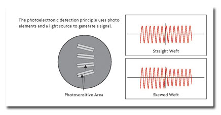
Photoelectronic Detection Principle
The photoelectronic sensor is based on a signal modulation created by the passing web
structure. One of the first photoelectronic sensors was based on several photo elements located on
one side of the web and a light source on the opposite side of the web. When the weft line was
parallel and straight in front of the sensor, a somewhat equally strong signal was generated in
both channels.
If the weft line was not parallel to the sensor, one pair of photo elements generated more
signal than the other, and this determined the distortion. That type of sensor could only
differentiate between left or right distortion and was not able to quantify the amount or angle of
distortion. Therefore, a proportional correction based on the physical distortion was not possible.
The next generations of optical sensors utilized only one photo element by letting it freely
oscillate between known limits. That improved the linearity, resolution and accuracy of each
sensor, enabling it to detect more complex fabric structures.
With microcomputers entering the industrial arena, it was not long until the first
microcontroller-based detection system was introduced. Stepper motor technology for linear movement
replaced the free-oscillation detection lens and improved lighting principles such as infrared
light-emitting diodes and reflex light sources, bringing the system more up-to-date.
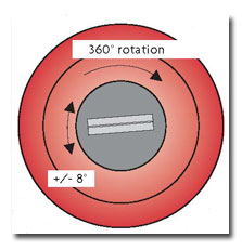
The photoelectronic detection technology is utilized in various executions such as
oscillation, rotation or shifted dual-rotating mode. By rotating the lens 360º instead of always
oscillating on the same position, one could avoid possible mechanical difficulties. However, there
is some valuable time lost by scanning areas of the fabric that are unrelated to the weft line. The
shifted dual-rotating mode reduces such time delays in collecting valuable weft distortion
information with a two-lens system.
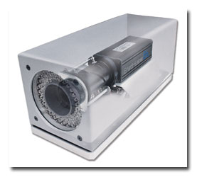
The latest CCD matrix camera from Erhardt + Leimer GmbH employs high-resolution auto-focus
and auto-zoom technologies.
Weft Detection Using Cameras
The rapid reductions in the prices of computer systems and digital cameras combined with
advanced image-processing techniques have led to the introduction of several vision systems to the
textile manufacturer. There are two types of camera systems that can be used to create an image:
line scan camera technology; or charged-couple device (CCD) matrix camera technology.
The line scan camera in combination with an encoder creates an image while the web passes
by. After capturing the image, the evaluation software uses special algorithms to process the
digital information.
The line scan camera technology typically is used to detect the full width of the web,
detecting and evaluating patterns rather than the weft line. That can be realized with either one
or two cameras, depending on the area of interest. However, if there is no pattern in the web, the
line scan technology is not able to detect any distortion in a web.
A matrix camera takes images similar to any conventional digital camera on the market. The
web is imaged several times per second, whether running or not, on a 2-D area. The camera looks at
multiple weft lines simultaneously, providing a high data rate of the passing weft structure. With
sophisticated software tools and mathematic calculation, a 3-D image is processed, detecting not
only the weft, but also the warp of a web.
The matrix camera technology is used for a closer look at the individual weft and utilizes
the weft structure in its calculation of the residual web distortion. Whether with several cameras
evenly distributed over the full width of the web, or just one scanning camera taking images
across, a large cross-direction and machine-direction profile of the passing web is captured. A
reflecting circumference infrared illumination guarantees the best uniform imaging results.
The latest camera introduced from Germany-based Erhardt + Leimer GmbH employs
high-resolution auto-focus and auto-zoom technologies that allow the camera to view an optimum
evaluation area and the largest 2-D area possible. The camera is mounted 250 millimeters away from
the web, moving it away from sometimes harsh existing environmental conditions. The image is then
processed within a 3-D space and filtered through a fast Fourier transformation (FFT), resulting in
spectral data. Separating the noise from the actual high-level spectral data leaves the positioning
information of the weft and the warp.
A major breakthrough of the 2-D image detection system using CCD matrix camera technology
makes detection on many difficult webs such as carpet, jacquard and thicker wefts a problem of the
past. Whereas conventional photoelectronic systems detect one weft at a time, the CCD matrix camera
has the ability to evaluate a large number of weft lines simultaneously, even if the web is not
moving. And whereas conventional photoelectronic sensors are required to have a minimum speed for
detection, the speed of the process has no influence on the final result or the quality of the
evaluated detection area when using the CCD matrix camera.
In addition to increasing the number of weft lines being detected, the system with its wide
field of view also has increased drastically the evaluation area in the cross direction of the
weft. That makes it more accurate and reliable because it sees far more than conventional detection
systems see.
Many disadvantages associated with conventional detection systems can be overcome by using
image-processing techniques to monitor webs of all kinds. New camera measurement systems have
improved the range of use from unstructured, homogenous webs to complex, patterned fabrics.
Higher-quality products and more satisfied customers result from more accurate and reliable
technologies.
Editor’s Note: Udo Skarke is manager of Germany-based Erhardt + Leimer GmbH’s Textile Division
in Duncan, S.C.